My apartment didn’t come with any lights, so I bought some tunable white LED panels from superbrightleds.com. The panels are controlled by RF remote controls. I wanted the color temperature of the lights to change automatically (on a schedule) to mimic sunrise and sunset. The obvious next step was to buy a HackRF One, reverse engineer the RF communication protocol, and spoof the transmissions from the remote control.

2’x4’ LED panel with remote control and wall switch
Hardware
Part numbers
These remarkably inexpensive LED panels and controllers are white-labeled by superbrightleds.com. They appear to be manufactured by “PLT” (Precision Lighting and Transformers), which is the house brand of 1000Bulbs.com. A bit of digging turns up the following part numbers:
| PLT part number | Description | superbrightleds SKU | 1000bulbs SKU | Price |
|---|---|---|---|---|
| LPRF22-40-NL | 2’x2’ panel | LPD-TWR22-40 | PLT-11231 | $65 |
| LPRF24-50-NL | 2’x4’ panel | LPD-TWR24-50 | PLT-11204 | $100 |
| RC24G | Remote control | LPD-TWHR | PLT-11206 | $10 |
| WM24G | Wall switch | LPD-TWWR | PLT-11205 | $10 |
There is also a brighter version of the 2’x4’ panel (72 W instead of 50 W), which is sold by superbrightleds.com but not listed in the PLT catalog at the time of this writing.
System architecture
The basic architecture of the system, inferred from the user guide, is that the LED panels are “receive only” and the remote controls are are “transmit only”. A panel is paired to a remote by switching on power to the panel while the remote is broadcasting a special pairing code. The panel has some non-volatile memory to remember which remote it’s paired with. The remote does not need any non-volatile memory (although it still needs some sort of factory-programmed unique ID). This is about what I’d expect from a remote control which only costs $10.
Surprisingly, though, the $10 wall switch is rather more capable. A wall switch can actually “clone” a remote control by listening to its pairing code. This allows an LED panel to be controlled by one or more wall switches while remaining paired with the primary remote control. (Although the manufacturer claims that a panel can be paired with at most one remote control and one wall switch, I have confirmed that an arbitrary number of wall switches may be used.)
| Component | RF capabilities | Non-volatile memory |
|---|---|---|
| LED panel | Receive only | Yes |
| Remote control | Transmit only | No |
| Wall switch | Receive and transmit | Yes |
Frequency band
Based on the “24G” in the part numbers and the utter lack of regulatory marks on the remote controls, I took a guess that the hardware uses the 2.4 GHz ISM band. I unboxed the HackRF and fired up CubicSDR to investigate the spectrum. Between my three remote controls, there were four different frequencies in use:
| Remote | Buttons | Center freq | Bandwidth |
|---|---|---|---|
| #1 | All except “ID” | 2445.0 MHz | 1.1 MHz |
| #2 | All except “ID” | 2440.0 MHz | 1.1 MHz |
| #3 | All except “ID” | 2437.0 MHz | 1.1 MHz |
| All | “ID” | 2434.0 MHz | 1.1 MHz |
A remote control is paired with a light fixture by holding its “ID” button while the light is turned on. Presumably, the light fixtures start up listening on 2434.0 MHz and retune to the frequency of the paired remote control after a brief time.
Unlike the remote controls, the wall switches do not have a fixed frequency. Each wall switch tunes its transmitter to match the remote control that it is cloning.
RF protocol
I fired up Inspectrum to examine the structure of the remote control’s transmissions. Each transmission is comprised of 2 millisecond pulses which repeat for as long as the button is held down. There are hints of repeating patterns within each burst, but because the symbol time is shorter than the Fourier transform window, the precise demodulated signal cannot be derived by visual inspection.
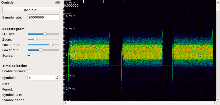
Horizontal-axis ticks are 1 millisecond each.
At this point it was time to bring the data into Python for analysis.
cmd = ['hackrf_transfer',
       '-r', '/dev/stdout',
       '-f', str(int(HACKRF_FREQ)),
       '-s', str(int(SAMPLE_RATE)),
       '-n', str(int(SAMPLE_RATE * CAPTURE_DURATION))]
raw = numpy.fromstring(subprocess.check_output(cmd), dtype='int8')
power = numpy.sum(numpy.square(raw, dtype='int16').reshape((-1, 2)), axis=1)
The raw data can be really huge, so it’s best to extract the 2 millisecond pulses before doing any other processing. I find the pulses by looking for continuous sections where the instantaneous power remains above a threshold.

is_valid = (power > MIN_SIGNAL_LEVEL**2)
is_valid[0], is_valid[-1] = False, False  # avoid edge cases
start_indices = numpy.where(is_valid[1:] & ~is_valid[:-1])[0] + 1
end_indices = numpy.where(is_valid[:-1] & ~is_valid[1:])[0] + 1
run_lengths = end_indices - start_indices
valid_runs = (run_lengths >= SAMPLE_RATE * MIN_PULSE_DURATION)
valid_indices = zip(start_indices[valid_runs], end_indices[valid_runs])
valid_slices = [slice(s, e) for s, e in valid_indices]
pulses = [raw[0::2][s] + 1j * raw[1::2][s] for s in valid_slices]
pulse_durations = run_lengths[valid_runs] / SAMPLE_RATE

It’s pretty clear from this plot that the signal is using frequency-shift keying. Now we can shift to baseband (by multiplying by a complex exponential). Inspection of the baseband signal reveals that the frequency shift is ±300 kHz from the center frequency. The next step is quadrature demodulation, which looks at the change in angle from one complex sample to the next.
signals = []
filt = scipy.signal.firwin(FILTER_LENGTH, 2 * FILTER_BW / SAMPLE_RATE)
for pulse in pulses:
    arg = numpy.arange(len(pulse)) * CENTER_FREQ / SAMPLE_RATE
    baseband = pulse * numpy.exp(-arg * 2j * numpy.pi)
    phase_change = numpy.angle(baseband[1:] / baseband[:-1])
    deviation = phase_change * SAMPLE_RATE / FREQ_SHIFT / 2 / numpy.pi
    smoothed_deviation = numpy.convolve(deviation, filt, 'same')
    signals.append(smoothed_deviation)

Next after demodulation is alignment and sampling. We can see that there are 10 samples per symbol, so the symbol rate is 1 MHz. The Fourier transform of the absolute value of the demodulated signal is evaluated at the symbol rate in order to align the sampling instants with the center of each bit.
messages = []
for signal in signals:
    samples_per_bit = SAMPLE_RATE / SYMBOL_RATE
    arg = numpy.arange(len(signal)) / samples_per_bit
    reference = numpy.exp(arg * 2j * numpy.pi)
    phase_product = numpy.angle(numpy.dot(numpy.abs(signal), reference))
    sample_offset = ((phase_product / 2 / numpy.pi) % 1.0) * samples_per_bit
    sample_moments = numpy.arange(sample_offset, len(signal), samples_per_bit)
    messages.append(signal[sample_moments.astype('int')])

Now we have all of the decoded messages stored in the messages
array. 0 and 1 bits are represented by negative and positive values,
respectively. There should not be any values very close to 0 – this
would represent a decoding error where it is not clear whether the bit
should be a 0 or a 1. We can check this by computing the minimum
absolute value:
symbol_separation = [numpy.amin(abs(m[50:-50])) for m in messages]
The symbol separation is a good check that the demodulation and sampling parameters were correct. In an ideal world, symbol separation would be exactly 1. In practice, symbol separation is reduced because the modulated signal is filtered to fit within a narrower channel. I obtain a minimum symbol separation of 0.55 when demodulating with correct parameters, and 0.00 when demodulating with incorrect parameters.
Here is the message I decoded for the “turn on” button from remote number 1:
11111111111111111111111111111111111111111111111111111111111110101010101010101010101011100011001100010010010000000010100011010001000001011111100101111000101000100111110000000011100111010010110001101100100001000100110001010011101011010100000100010010110110001001111000011001011100100111111000000011000101110001010000010000101001110111001011001001001110001000101100001100101011010000000110011111001011100110101101010010101111100001000000011000001110001110111000101100100110100100011100010111101001110011000000100101110001000101000101100001001110001000101100001100101011010000000110011111001011100110110100110101001010111110000100000001100000111000111011100010110010011001001110001000101100001100101011010000000110011111001011100110100011001011000010100100100010100111111000100100010001100011100010100010111000011111010000000010101001000010111011110011100110100001001110001000101100001100101011010000000110011111001011100110100100111000100010110000110010101101000000011001111100101110011010100010111000011111010000000010101001000010111011110011100110100100010011110011000000110000010010100101111011001101010101011100110001001111001100000011000001001010010111101100110101010101110010010011100010001011000011001010110100000001100111110010111001101001001110001000101100001100101011010000000110011111001011100110100100111000100010110000110010101101000000011001111100101110011010100100011100010111101001110011000000100101110001000101000101100010000000001100000111101101001110001000100011101001000000101110100100111000100010110000110010101101000000011001111100101110011010010011100010001011000011001010110100000001100111110010111001101000110010110000101001001000101001111110001001000100011000111000100100110000001101011110000110110100001110010101110001000000001010010011000000110101111000011011010000111001010111000100000000101010011111100000001100010111000101000001000010100111011100101100110001001111001100000011000001001010010111101100110101010101110011001100000110001111111000101010100101010110010001010010010100100001011
It’s easy to reverse this process and generate a signal for transmission from the binary message:
# Generate the baseband frequency-shift-keyed signal
assert SAMPLE_RATE % SYMBOL_RATE == 0.0, 'must have integer samples per bit'
phase_direction = numpy.repeat(numpy.where(message, 1, -1),
                               SAMPLE_RATE // SYMBOL_RATE)
arg = numpy.cumsum(phase_direction) * FREQ_SHIFT / SAMPLE_RATE
baseband = numpy.exp(arg * 2j * numpy.pi)

# Apply light smoothing to remove high frequency components
filt = scipy.signal.firwin(FILTER_LENGTH, 2 * FILTER_BW / SAMPLE_RATE)
smoothed_baseband = numpy.convolve(baseband, filt, 'full')

# Shift the signal away from baseband and amplify it
arg = numpy.arange(len(smoothed_baseband)) * CENTER_FREQ / SAMPLE_RATE
signal = numpy.exp(arg * 2j * numpy.pi) * smoothed_baseband * OUTPUT_AMPLITUDE

# Repeat the signal and convert to raw int8 I/Q samples
total_samples = len(signal) + int(BLANKING_TIME * SAMPLE_RATE)
output = numpy.zeros((NUM_REPETITIONS, total_samples, 2), 'int8')
output[:, :len(signal), 0] = numpy.around(numpy.real(signal))
output[:, :len(signal), 1] = numpy.around(numpy.imag(signal))

# Write the output
cmd = ['hackrf_transfer',
       '-t', '/dev/stdin',
       '-f', str(int(HACKRF_FREQ)),
       '-s', str(int(SAMPLE_RATE)),
       '-x', str(SDR_TX_GAIN)]
p = subprocess.Popen(cmd, stdin=subprocess.PIPE)
p.communicate(output.tobytes())
p.wait()
It works! The lights turn on when a synthesized message is transmitted. (And any hackers in the area who read this website and have a software-defined radio can now turn on my kitchen lights.)
Digital message encoding
The last step is to understand the meaning of the 2000-bit message by studying which bits change for different commands and for different lights. I haven’t gotten around to this yet. Send me an email if you’d like to help!