The purpose of this project was to allow unlocking my apartment door using the same RFID tag which opens the apartment building’s front door. Prior to this project, the apartment door was unlocked using a regular pin-tumbler key.
After writing embedded firmware in C for more than a decade, I also used this project as my first opportunity to write a microcontroller firmware in pure Rust.
Door hardware
My door has an integrated mortise lockset with latch and deadbolt. The standard solution for electric release would be a commercial electric strike such as the Von Duprin 6400:
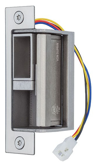
But there are a few problems with this type of strike. First is the cost (about $400). Second is the required modification to the door frame (cutting away the inside edge), which I’d like to avoid. And finally, there is a structural beam in my wall which leaves only 25 mm of clearance behind the face of the door frame. An off-the-shelf mortise strike simply won’t fit.
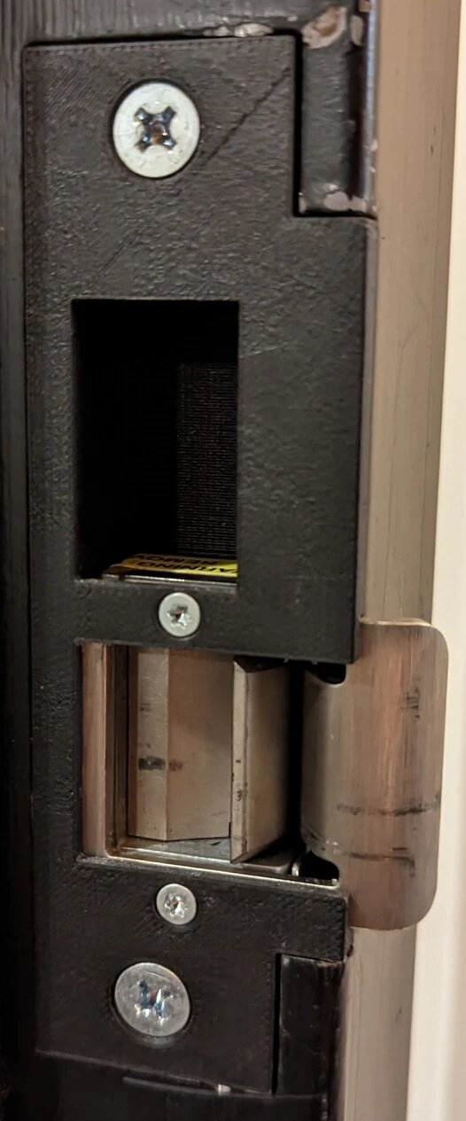
I found that the Seco-Larm SD-991A-D1Q mini electric strike is small enough to fit around the latch without interfering with the deadbolt. It uses a “no-cut” ramp design to avoid having to modify the door frame.

I designed a 3D printed adapter to hold the Seco-Larm strike in the right place. It’s modeled in OpenSCAD, then printed out of Markforged nylon with continuous carbon fiber reinforcement.

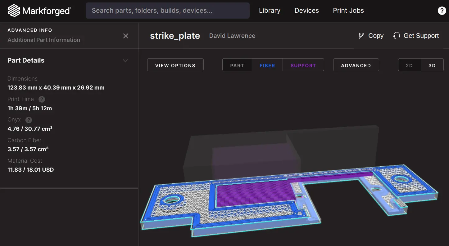
The total cost of this solution is lower: $60 for the strike and $20 for the adapter and hardware.
That’s all for the door hardware side of things. Now we need a RFID reader to put 12 volts into the Seco-Larm strike when it’s time to unlock the door.
RFID hardware
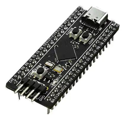
My goal was to use inexpensive off-the-shelf parts as much as possible. The brains of the RFID reader are the ubiquitious STM32F411 “black pill” microcontroller breakout.
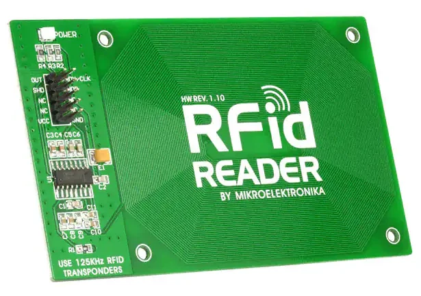
For the RF front end, I chose the Mikroe 262 breakout board for the EM4095 driver/demodulator IC. This low-level reader provides enough flexibility to detect the AWID RFID tags which are already used for the front door of my apartment building.
Finally, to energize the electric strike from a USB power supply, I selected a boost converter module and added an external switching MOSFET and a flyback diode.
Bill of materials
| Description | Digikey part number | Cost |
|---|---|---|
| Mikroe 262 RFID reader | 1471-1165-ND | $24 |
| STM32F411 black pill | 1738-DFR0864-ND | $15 |
| Recom RS6-0512S boost module | RS6-0512S-ND | $15 |
| Plated through-hole breadboard | 1738-1001-ND | $3 |
| N-channel MOSFET | FQP30N06L-ND | $2 |
| Schottky diode | 1655-SB160CT-ND | $0.5 |
| Ribbon cable connector | ED1543-ND | $0.5 |
| Total | $60 |
Schematic
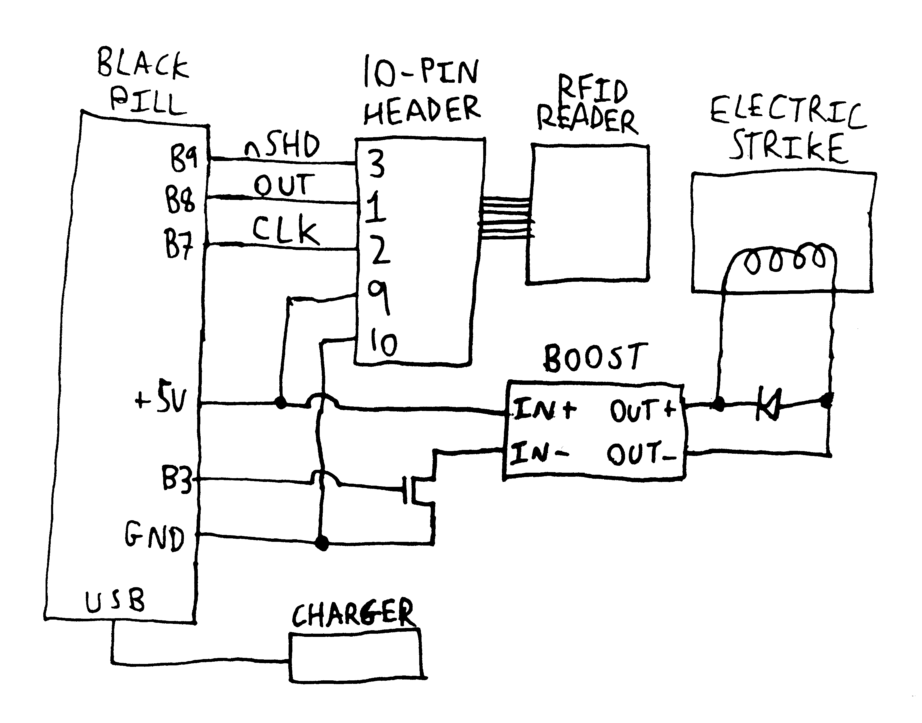
I removed the series protection diode from the STM32F411 black pill, replacing it with a 0 ohm resistor. This raises the 5 volt rail from 4.8 volts to a true 5 volts.
I found that the Mikroe 262 antenna was poorly tuned, running at about 110 kHz. I reduced capacitor C7 from 1.8 nF to 1.2 nF to increase the resonant frequency to the nominal 125 kHz.
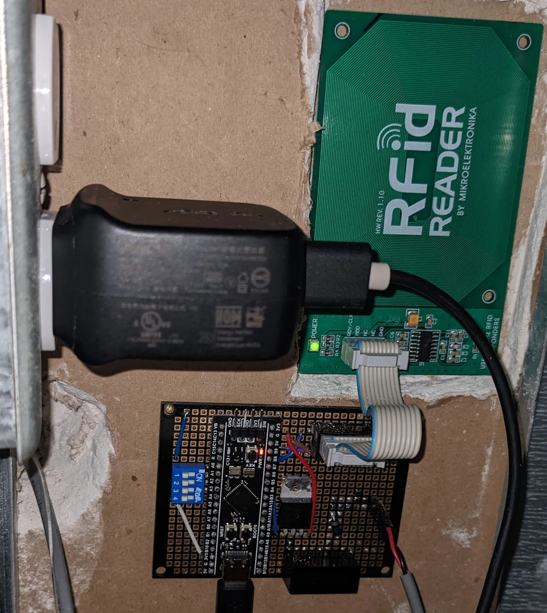
Putting it all together
Rust firmware
With all the hardware assembled, it was time to write firmware. I decided this was a good project to use as my first foray into Rust. Here’s a walk-through of my Rust code, combined with some musings about Rust as an embedded systems language.
The complete firmware for this project is available on Github.
Project setup
I started out with the embedded application template from Ferrous Systems, then stripped out the parts I didn’t want to use.
What remains is the following set of files:
Cargo.toml– I found it fairly tedious listing out all my dependencies and their versions here. But I suppose that’s the price to pay for having dependency management automatically handled by Cargo.memory.x– Most of the linker script is automatically provided by other packages, but each project must provide its own definitions of the FLASH and RAM memory regions..cargo/config– Easy to miss, because it’s in a hidden folder, but this file does two important things: it sets the target CPU architecture, and it adds the provided linker script into the linker flags. This needs to be separately present in every embedded project.src/main.rs– The business of the application.
Overall the installation and setup process was pretty easy. Certainly much friendlier than C, where it’s considered normal to start a new project by writing your own makefile and linker script from scratch. The quality of community-contributed Rust documentation is excellent, and that extends to the embedded-specific documentation.
RTIC
RTIC is a remarkable embedded framework that’s available in Rust. It uses a very pleasant model of concurrency-via-interrupt-priorities that allows safe access to shared resources, with minimum overhead, with safety guaranteed at compile time. It’s really quite nice.
The drawback, and it’s a big one, is that RTIC is implemented as a giant macro that transforms the application code. The application syntax is still Rust, but there’s a little bit of non-idiomatic stuff and a lot of semi-undocumented magic happening behind the scenes.
I still find RTIC a lot nicer than alternatives such as a true
bare-metal application (too much unsafe required) or Embassy (too
far removed from the hardware), but it’s been a bit of a journey
figuring out how to work with it.
The application
Let’s go through main.rs from the top, one chunk at a time.
Preliminaries: no standard library, no main function, and use the RTT embedded communication library to signal a panic if one should occur.
#![no_main]
#![no_std]

use panic_rtt_target as _;
Now the RTIC magic starts. #[app...] is an attribute macro that
transforms the source code of the entire program which follows.
use rtic::app;

#[app(device = stm32f4xx_hal::pac, peripherals = true, dispatchers = [SPI1])]
mod app {
One RTIC oddity is that the entire application lives inside a module,
so library imports (use statements) need to be located within the
module rather than placed at the top level of the file. I’m still
figuring out a good balance between listing all the imports explicitly
and useing a bunch of wildcards.
    use core::sync::atomic::{AtomicBool, Ordering};
    use dwt_systick_monotonic::{fugit, DwtSystick};
    use rtt_target::{rprintln, rtt_init_print};
    use stm32f4xx_hal::{gpio::*, pac::*, prelude::*, timer::Timer};
The fugit library for time handling is quite nice, although
documentation is sparse. Clock setup is not totally automatic, so we
have to use the constant CLOCK_FREQ_HZ in multiple different places
during setup.
    const CLOCK_FREQ_HZ: u32 = 48_000_000;
    type Duration = fugit::Duration<u32, 1, CLOCK_FREQ_HZ>;
    type Instant = fugit::Instant<u32, 1, CLOCK_FREQ_HZ>;
Next up are a few constant declarations for the actual business of
reading RFID cards. I think it’s cleaner to put these up top for
visibility. There are 100 RFID clock edges per bit, 96 bits in the
entire modulated message of an RFID tag, and a specific 96 bit pattern
which unlocks the door. For an AWID26 card, the CARD_SEQ here is
exactly the same as the raw value reported by the Proxmark3 client.
    const CLOCK_EDGES_PER_BIT: u16 = 100;
    const CARD_SEQ_LEN: usize = 96;
    const CARD_SEQ: u128 = 0x11abcdabcdabc1111111111; // bogus value
RTIC requires us to put all our shared variables into these two
special (magical) structs: shared for variables which could be used
by multiple interrupt handlers, and local for variables which will
be set up by init and then used exclusively by a single handler.
Perhaps counterintuitively, “shared variables” includes any hardware
peripherals which need to be accessed by handlers post-init.
    #[shared]
    struct Shared {
        request_unlock: AtomicBool,
    }

    #[local]
    struct Local {
        led: Pin<'C', 13, Output<PushPull>>,
        latch: Pin<'B', 3, Output<PushPull>>,
        rfid_out: Pin<'B', 8, Input>,
        timer: TIM4,
    }
Another piece of RTIC magic is the definition of the required monotonic timer type.
    #[monotonic(binds = SysTick, default = true)]
    type Tonic = DwtSystick<CLOCK_FREQ_HZ>;
The init function runs at startup and is responsible for creating
all of the shared variables. In Rust, this means init receives a
Peripherals object and breaks it down into separate objects for each
GPIO and other peripheral which the remainder of the program will use.
    #[init]
    fn init(mut ctx: init::Context) -> (Shared, Local, init::Monotonics) {
        rtt_init_print!();
        rprintln!("door running");

        // System clock and monotonic timer
        let rcc = ctx.device.RCC.constrain();
        let clocks = rcc.cfgr.sysclk(CLOCK_FREQ_HZ.Hz()).freeze();
        let mono = DwtSystick::new(
            &mut ctx.core.DCB,
            ctx.core.DWT,
            ctx.core.SYST,
            CLOCK_FREQ_HZ,
        );

        // GPIO pins
        let gpiob = ctx.device.GPIOB.split();
        let gpioc = ctx.device.GPIOC.split();
        let _rfid_nshd = gpiob.pb9.into_open_drain_output_in_state(PinState::Low);
        let _rfid_clk = gpiob.pb7.into_alternate_open_drain::<2>(); // TIM4 TI2
        let mut rfid_out = gpiob.pb8.into_pull_down_input();
So far I’ve been using the high-level HAL crate to set up all peripherals. The timer will be used as an edge counter, which is not a mode that the HAL supports (yet). Instead, we have to take the TIM4 peripheral object back from the HAL and configure its registers manually. This weird closure builder interface is probably my least favorite part of the entire embedded Rust ecosystem.
        // Configure TIM4 as a hardware counter for CLK edges using TI2 input.
        // Register configuration per ST RM0383, section 13.3.3.
        // Use the HAL to enable and reset, then release for manual register config.
        let timer = Timer::new(ctx.device.TIM4, &clocks).release();
        timer
            .ccmr1_input()
            .write(|w| w.cc2s().ti2().ic2f().bits(0b0011));
        timer.ccer.write(|w| w.cc2np().set_bit().cc2p().set_bit());
        timer.smcr.write(|w| w.sms().ext_clock_mode().ts().ti2fp2());
        timer.cr1.write(|w| w.cen().set_bit());

        // Enable edge-triggered interrupt for RFID OUT pin
        rfid_out.make_interrupt_source(&mut ctx.device.SYSCFG.constrain());
        rfid_out.enable_interrupt(&mut ctx.device.EXTI);
        rfid_out.trigger_on_edge(&mut ctx.device.EXTI, Edge::RisingFalling);
In one final piece of RTIC boilerplate, we have to assemble all the shared variables into their respective structs and return them.
        (
            Shared {
                request_unlock: AtomicBool::new(false),
            },
            Local {
                led: gpioc.pc13.into_push_pull_output_in_state(PinState::High),
                latch: gpiob.pb3.into_push_pull_output_in_state(PinState::Low),
                rfid_out,
                timer,
            },
            init::Monotonics(mono),
        )
    }
The idle function runs continuously whenever there’s not another
interrupt doing something. For the RFID reader, it checks if the
request_unlock flag is set, and sets the GPIO accordingly.
This is a nice example of Rust’s Option type being put to good use.
If the door is unlocked, unlock_until is the time the door should be
re-locked. If the door is locked, unlock_until is None. This is
more straightforward than using two separate variables to store the
re-locking time and the current door state, and the compiler makes
sure that we always check the lock state prior to accessing the relocking
time.
    #[idle(shared = [&request_unlock], local = [led, latch])]
    fn idle(ctx: idle::Context) -> ! {
        let mut unlock_until: Option<Instant> = None;
        loop {
            if ctx.shared.request_unlock.swap(false, Ordering::Relaxed) {
                rprintln!("unlock");
                unlock_until.replace(monotonics::now() + Duration::secs(1));
            } else if let Some(t) = unlock_until {
                if t < monotonics::now() {
                    rprintln!("lock");
                    unlock_until.take();
                }
            }
            let unlock = unlock_until.is_some();
            ctx.local.led.set_state(PinState::from(!unlock)); // LED inverted in hardware
            ctx.local.latch.set_state(PinState::from(unlock));
        }
    }
The one and only interrupt handler fires on edges of the demodulated
signal. It grabs the clock edge count from the timer, and then does
some cute lightweight processing on the edge times to decode the bits.
If there’s a match with CARD_SEQ, we set the request_unlock flag.
    #[task(binds = EXTI9_5, shared = [&request_unlock], local = [
        rfid_out,
        timer,
        last_edge_times: [u16; 12] = [0; 12],   // units of CLK edges (TIM4 counts)
        last_bit_end_time: Option<u16> = None,  // units of CLK edges (TIM4 counts)
        demodulated_bits: u128 = 0,
    ])]
    fn on_exti(ctx: on_exti::Context) {
        ctx.local.rfid_out.clear_interrupt_pending_bit();
        let clk_count: u16 = ctx.local.timer.cnt.read().cnt().bits();
        let edge_times = ctx.local.last_edge_times;
        let bit_end_time = ctx.local.last_bit_end_time;
        let elapsed_time = bit_end_time.map_or(CLOCK_EDGES_PER_BIT, |t| clk_count.wrapping_sub(t));
        if elapsed_time >= CLOCK_EDGES_PER_BIT + 10 {
            *bit_end_time = None;
        }
        // Modulated zero bit: 8 clock edges per data edge
        // Check if the last 12 data edges covered 96 +/- 3 clock edges
        let zero_time = clk_count.wrapping_sub(edge_times[11]);
        let zero_bit = 93 <= zero_time && zero_time <= 99;
        // Modulated one bit: 10 clock edges per data edge
        // Check if the last 10 data edges covered 100 +/- 3 clock edges
        let one_time = clk_count.wrapping_sub(edge_times[9]);
        let one_bit = 97 <= one_time && one_time <= 103;
        if (elapsed_time > CLOCK_EDGES_PER_BIT - 10) && (zero_bit || one_bit) {
            *bit_end_time = match bit_end_time {
                // 1.25 kHz modulation: 100 clock edges per modulated bit
                Some(t) => Some(t.wrapping_add(CLOCK_EDGES_PER_BIT)),
                None => Some(clk_count),
            };
            let bits = ctx.local.demodulated_bits;
            *bits = (*bits << 1) | (one_bit as u128);
            if *bits & ((1 << CARD_SEQ_LEN) - 1) == CARD_SEQ {
                ctx.shared.request_unlock.store(true, Ordering::Relaxed);
            }
        }
        edge_times.rotate_right(1);
        edge_times[0] = clk_count;
    }
}
A few other Rust-isms worth noting in this:
wrapping_addand other aspects of overflow handling- Quality-of-life functions such as
array.rotate_right()(note that link-time optimization needs to be enabled to avoid significant overhead from this call) - Interior mutability of the
AtomicBooltype – a regularboolcould not safely be used here
And that’s it… less than 150 lines of code for the full application. Not bad!
Tooling
The cargo embed command automatically builds, flashes, and executes
the application on an attached embedded target. Gone are the days of
fiddling with long OpenOCD commands in a bespoke makefile. One
additional file (Embed.toml) is required to configure the
microcontroller part number, then everything “just works”.
Future work
I’d like to increase the RFID read range by boosting the antenna voltage. I’ll probably spin a custom PCB with an EM4095 on it. Maybe I’ll integrate the microcontroller also?
Maybe I’ll add on-board tag sequence storage in runtime-written flash, so it’s easier to authorize a new tag to unlock the door.
Perhaps I’ll add an internet connection, to allow remote opening? (Although I’m really not a fan of putting things on the internet, in general.)